|


| Quantity: | |
|---|---|
DTS3666
YONY OR OEM
Specifications and Parameters
1.Specifications
2. Basic Error(balanced load basic error limit)
Note:(Ib is basic current In is rated current Imax is maximum current)
The error limit(%) between each current point with unbalanced load: Class1,±2.0; Class2,±3.0
3.Starting
When the rated voltage, rated frequency and power factor is 1.0, the loaded current is 0.004Ib(class1)、0.005Ib(class2), the meter shall starts and measures energy continuously.
4.Creeping
When the voltage circuit is loaded with a voltage 1.15 times of the rated voltage and there is no current in the current circuit, the meter is supposed not to output more than one pulse.
5.Working Voltage Range
Normal Working Voltage:0.9Un~1.1Un
Working Voltage Limit:0.0Un~1.15Un
6.Power Loss
Power loss of the voltage line in each phase≤2W/10VA
Power loss of the current line in each phase≤4.0VA
7.Environment condition
standard working temperature:-40℃~+75℃,
working temperature limit:-45℃~+80℃
Storage and transport temperature limit:-25℃~+70℃
Relative humidity: annual average≤75%
Protection Rank:IP54
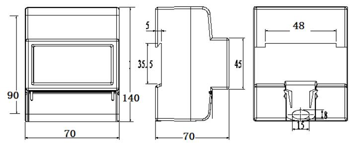
8.Configuration and Dimension